BMW motorcycle valve adjustment procedures |
|
Why adjust BMW motorcycle valves?Valve adjustment is one of the most misunderstood maintenance items on the BMW. You are really performing a diagnostic function. For example, the engine will run very well with a setting of exactly zero clearance up to double the spec. With zero clearance, the valves will open a bit more and allow more fuel into the combustion chamber and that will make more hp, but you may not be able to measure it with a dyno. Really wide spacing will make more noise and not allow as much fuel into the combustion chamber, but again, you probably can't measure it. The wider clearance will make more noise. The main reason to do the valve adjustment is to check for a change in settings from the previous time. If one or more valves are more than .001" off of where they were last set, you better make a notation in your log book. If a dozen people set your valves, they would each do it slightly differently. Which method is right? All are probably right. The important thing is to do it exactly the same from one adjustment to the next one. Then, any change shows you that something must be diagnosed to look for more serious problems. If you find that the valves all still have a correct setting, this means that the heads are stable. If that is the case, then there is no reason to check the torque on the head nuts. All you will have done is remove the valve covers, check settings and replace the covers. And be happy. If you found some change in the settings, then ask why? Reset them and check them again soon to see if it still changes. Find out why it is changing. The "famous" BMW motorcycle rocker arm alignment tool for the /5The /5 came out in 1970 and one of the highly criticized things about the "new model" was its very noisy valves. The first attempt, by BMW, to do something about this was the alignment tool for the rocker arms.
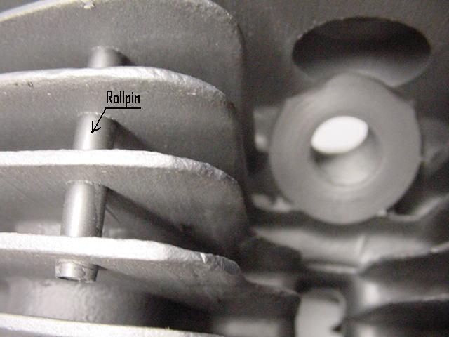
The factory supplied rocker arm alignment tool. It came in another version and both are completely worthless. It was introduced in late 70. The proper use of the tool made almost no difference in the noise of the valve system. If a rocker arm was way off from where it belonged, then the pushrod could rub and make some noise. All that one needed to do about this is to have the pushrod about centered in the hole in the head. Just look at where it emerges from the head and have it about in the center. When the engine rotates, the push rod will move up and down in the hole a bit. All that you are trying to do is to keep it away from the edges of the hole as much as possible. The hole in the head gasket may not quite line up with the hole in the head. It is possible for the push rod to touch the head gasket and make a shiny place on the rod. This "touching" may make some noise. Loosen the two nuts on the rocker arm so that you can move it slightly and torque them back down. The second attempt (after the first failed) to do something about the valve noise was in 72 with the addition of the roll pins in the fins of the heads. The fins were "ringing" and sort of amplifying any valve noise. This worked well for reducing whatever amount of noise existed, but did nothing about the reason for the noise. Additional noise can be reduced by adding in plugs between the fins, much like the roll pins.
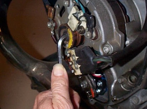
Here you can see the roll pin on the left side and the spark plug hole on the right. Photo by Randy, thanks. Early on we discovered that the "source" of the noise was coming from the excessive end play of the rocker shafts. More about this below. How to adjust BMW valvesThis page will describe the way the mechanics at BMW of Marin, my dealership, adjusted valves on /5 BMWs. Shown is a modified /5 engine, but for valve adjustment purposes it is all the same. Almost all of our valve adjustments were done as part of a larger procedure, a "tune-up" or a "full service." The plugs would be out for inspection, cleaning or replacement. The front engine cover would be off for ignition timing. Valves can be adjusted in several ways and in a different order than described here. Establish your pattern and stick to it as much as possible. Record your findings. There are three commonly accepted ways of turning the engine to get it to the correct spot for this adjustment. 1. Remove the spark plugs and turn the engine with a 6mm Allen wrench in the alternator mounting bolt. 2. Put the transmission in gear and turn the rear wheel. 3. Use the kick starter to gently "bump" it around. It doesn't really make much difference. For commercial purposes we can't waste the customer's time, so we chose # 1. You did dab a spot of white paint on each flywheel mark, didn't you? According to BMW, the engine must be cold. The /2 and earlier often had unstable heads and the valve adjustment would/could change easily with temperature. If your /5, or later engine, is healthy, it matters none of it is hot or cold. The settings will be virtually the same. These heads are stable and temperature isn't important. If you find a difference of more than .002", then I would want to know why. Most of this procedure is for checking BMW valve lash (clearance) for the first time. 1. Remove the valve covers and catch the oil. Notice the tightness of the nuts. The center nut should not be as tight as the two smaller outer nuts. Each side of a valve cover should have some oil in it. Some gray paste is usually found settled out from the oil. Check that there is no chips of metal in the paste. If you find no oil, this is serious and it is time to do some troubleshooting. 2. Remove the spark plugs. Notice the tightness. The spark plugs should not be very tight, just good and snug. 3. Remove the front engine cover. One must remove the battery ground cable to protect the diode board and other electrical components. The cover can easily short out electrical connections on the way off. The horn may get in the way too. 4. Use a 6 mm Allen wrench, in the center of the rotor, to turn the engine. Don't leave the wrench in the rotor. Don't ask.
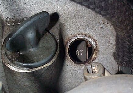
Turn the crankshaft until the spark advance unit looks like this.
5. The angle of the advance is what I call 10 and 4 O'clock. When the advance unit looks like this, the crankshaft is very close to top dead center (TDC). 6. Turn the crankshaft back and forth until you see the TDC mark in the window. The mark says OT. If needed, use white paint on the mark for better visibility. The mark doesn't need to be in the exact center of the window. It will look like this.
7. One side or the other is ready for adjustment. How do we know which it is? The side that is in position for adjustment will have both valves closed. Rock the crankshaft back and forth and one side will show the rocker arms moving and the other side won't move at all. The one that doesn't move is the one. Another way is to rotate the pushrods with your fingers. One side's pushrods should easily turn and the other side just won't. The side that turns easily is the one at TDC and ready for adjusting. Using feeler gauges, check the valve clearance. If it is within spec, then you know that it didn't move since last time and you are done with that side. 8. Now is a good time to observe the dreaded rocker arm alignment. The pushrods must move in and out without hitting anything on the sides. If it hits something it will make noise. The worst case I have seen actually hit so long that it began wearing the pushrod down to a thinner size. It hadn't yet collapsed, but it eventually would. As the pushrod moves out to actuate the valve it moves lower compared to the hole. At this point we want to see it a bit above the center of the hole. It should be fairly centered in the horizontal plane, that is, right and left. If the pushrod is very far off, it should be fixed. BMW made a tool for this, but it takes too much time and isn't needed to get the accuracy required. One can get it just as accurate by eye. It should look like this.
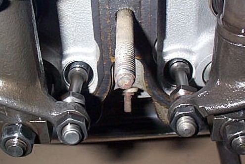
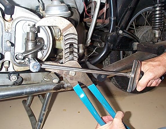
9. Before we fix that, we must look at something else. Check the end play of the rocker arm on it's shaft. If it is loose, it will make valve noise. Grab the rocker arm and gently, at first, shake it up and down. It should not move at all, not even .010." It is possible for a noisy valve to be as much as 1/16" loose. Now you have discovered that the rocker arm has a bit too much end play. You want to fix it. Now some theory. 10. If this is your first time adjusting the valves on this engine, I suggest checking the torque on the 6 fasteners, 4 nuts and 2 bolts. I would break them loose and watch the beam torque wrench readings. Then slowly tighten it up to 25 lbs. Now go to the next one. The order is not important, as there are so few of them. The engine is cold. The head is made of aluminum. Aluminum has an interesting characteristic called cold flow. If it is put under some stress it will slowly conform to relieve the stress. For example; if we removed the torque on one head bolt and left it overnight, it might (probably not) be enough for the head to warp. A warped head is a problem. If we remove the torque from one or more head bolts for a few minutes, nothing will happen. That is what we do for this adjustment. On the rocker arm that has the mis-aligned pushrod, back off the two head nuts. Measure the torque that it takes to "break" it loose. It should be about 25 lbs. Apply torque slowly for this measurement. If it is very far off, be cautious and consider that other nuts may be off too. It shouldn't be over 25 ft. lbs. One risks pulling the head bolt out of the engine case, not good. I would much rather find a nut at 20 lbs. than 30 lbs. (BMW had rocker shaft end blocks that were a very tight fit in 70-71 or so. Later they went to one with a split in it. They didn't need to be held tightly while torquing the head.) Now you have the 70-71 rocker arm loose and it needs to be "held" while the nuts are tightened. Here is how we did it.
11. That is a giant pair of adjustable pliers. It is tricky to pinch the blocks on the ends of the rocker arms just the right amount while applying torque to the nuts. Sometimes the blocks resist being pinched together and I resort to a tap with a hammer on the top and bottom jaw of the pliers. Between the end block and the rocker arm is a wave washer. Tighten the nuts up a bit to hold everything in place and check for end play. Check the arm to see that it still rotates a bit and freely. It may be required to loosen up the valve adjustment somewhat to allow enough movement to see the rotation and that it is smooth. The up and down play should be gone. The pushrod must still be centered in the hole. It is a lot of things to get right all at once. The first time you may need a "third hand". My hand position shown is only for the photograph. I actually have the torque wrench vertical and upside down. When you are happy with the position of the rocker arm and pushrod, torque the nuts to 25 ft. lbs. Pull them up slowly to 25 lbs. The split type rocker arm end blocks can be held by hand. Check the other rocker arm on that side for alignment and correct as needed. Rotate the engine and do the other side. 12. Now is the time to check and adjust the valves. Find the specification for your bike and the appropriate feeler gauge. The /5 is .006," or .15 mm for the intake and .008," or .2 mm for the exhaust. The valve gap, or lash, is not really important in the operation of the engine. The /2 had valve adjustment that drifted all over the place. BMW could have just been cautious on the first /5 and suggested a large clearance at first. Later on they learned that the heads were stable. With the /7 they used a tighter setting and it was no problem. I use a feeler gauge from BMW tool kit. The size was once marked on each gauge, but now it is probably invisible. Of the four feelers, use the thinnest one for intake and the slightly thicker one for the exhaust. Insert the gauge into the space between the rocker arm and the end of the valve. Sometimes it is easier to get it in if you push on the other end of the rocker arm, which is against the pushrod. That will take up any free play in the system. Don't worry, you won't crush the pushrod.
13. This photo shows the left side of the engine and tools working in the intake valve. My left hand is holding the 12mm open end wrench and that thumb is pushing on the pushrod. My right hand is holding the feeler gauge. The open end wrench is on the inside bolt. The outside nut is the jamb nut for holding the bolt in place. 14. Here is place for you to develop your style. I prefer the feeler to go through with some drag. If it is too easy then you don't really know that you have taken up all of the play. It definitely shouldn't fall out of it's own weight. The important thing is to always do it with the same amount of drag on the feeler. Don't obsess over this. The difference between a really tight setting and a slightly loose one is probably less than .001." If you are off by .002" and all else is OK, then no large change in noise will occur. No engine failure will occur. 15. Each time that one checks the valves, it is not to correct some small error, but to discover if the setting is changing between adjustments. Record any significant change and be sure to check it again in 1000 miles or so. If the change is measurable in 1000 miles, then something is wrong and you have found it before it failed on the road, at night and in the rain. Check it often and log the change. Get ready to spend money. 16. Now to actually adjust the valve. On the left end of the rocker arm, in the last photo, is an adjustment. See that bolt and nut? Loosen the (outside) jamb nut. Slowly move the bolt a tiny bit. A quarter of a turn is a large amount. Once you feel good about the drag on the feeler, tighten up the nut while still holding the bolt. It should be tight, but not over tight. I tighten mine to about 15-18 lbs. of torque. If this one is over tightened it will strip the threads on the bolt. Now check the feeler gauge again. If it's not what you wanted, try again. It takes some fiddling around to learn where to have it to get it correct after it's tightened up. 17. Do the exhaust valve too and you have finished one side and it's time for the other side. Turn the crankshaft one full turn and the advance unit will go around 1/2 turn to the same 10-4 position. In the case of my photo, the red paint would appear on the other end. Find the OT mark in the window. Again check the pushrods to be sure that they will rotate easily. A few notesThe valve cover gasket is good for life. They only need replacing when someone screws them up, usually by removing them. I just leave them stuck to the head. Installing the valve cover can be easily screwed up. Don't over tighten the three fasteners. I just did this job on my bike to try to remember each step, photograph and measure the tightness of things. The two 10mm nuts on the backside of the valve cover are hard to measure, but I just bring them up to snug. The center 13mm fancy nut is even more important to get just snug. My 0-50 lb. 3/8" drive beam type torque wrench won't even register torque as small as is needed on all three fasteners on the valve cover. I would estimate it to be 2-3 lbs. Very few fall off, but lots fall out with the stud, because the center nut was over tightened and it pulled the stud out of the head. Now you do have a problem. It is better to lose only a nut than all three, the nut, washer and stud plus the threads in the head. If the center stud falls out, or is missing, don't panic. The two outer 10 mm nuts will probably hold the cover on well enough that it doesn't leak oil. You can ride the bike until you get around to repairing the hole with Helicoil or other suitable thread repair product. When tightening the three 5 mm Allen bolts on the front cover, just make them snug. I couldn't measure them either. I have never heard of a front cover falling off. Install the spark plugs with a thin coating of anti-seize on the threads. Don't over tighten them either. Mine are in the 10-15 lb range. No customer has ever reported to me that one of our tune-up jobs resulted in a plug falling out. I have seen many heads that had stripped out threads from over tightening. The BMW shown is a collection of parts from many years and models. Many items
are left off, such as horn, turn signals, front brake switch, wiring harness,
instruments and more. Other anomalies may be seen, but for valve
adjustment instruction purposes these photos are valid. |
|
This page was last edited:
07/13/2006 - copyright
Duane Ausherman |